
About:
In this project i will explain how to interface MFRC522 based RFID read/write module RC522 with Arduino (arduino uno in my case). The example code is designed to read RFID tag unique number and identify the desired tag among’s them. A piezo buzzer and neopixel is also used in this project for visual and audible indication. Serial port is also programmed to view output in arduino IDE serial monitor.
Components:
- RFID-RC522 13.56MHz read/write module

- Arduino Uno
- Neopixel
- Piezo Buzzer
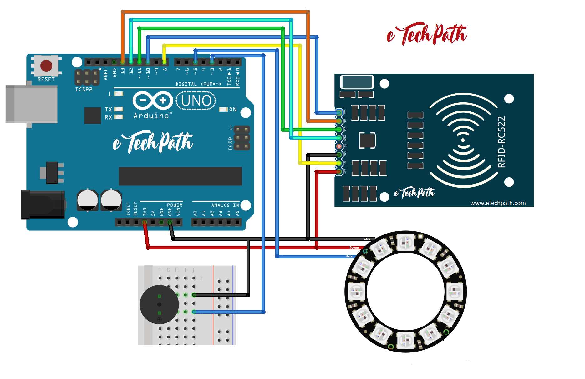
Circuit Diagram:
![]()
Description:
-
- RFID-RC522: This RFID module is designed to work on 3.3v (voltage level 2.5v to 3.3v). So, do not connect this module to arduino’s 5.0v supply. Other that power supply, connect all SPI interface pins to arduino as shown in the circuit diagram or refer bellow table.
.
RFID Pins     Arduino Pins
   SDA           10
   SCK           13
   MOSI          11
   MISO          12
   IRQ           NC
   GND           GND
   RST           8
   3.3v          3.3v
- RFID-RC522: This RFID module is designed to work on 3.3v (voltage level 2.5v to 3.3v). So, do not connect this module to arduino’s 5.0v supply. Other that power supply, connect all SPI interface pins to arduino as shown in the circuit diagram or refer bellow table.
-
- NeoPixel: Neopixel can work on both 5.0v or 3.3v. But 5.0v is better option to drive neopixel to obtain maximum brightness (in this project i have connected it with 3.3v for ease of circuit). So, connect neopixel power and ground with arduino and connect data line to arduino pin 5 as shown in the circuit diagram. Note: Here in this project i am using 12 pixels neopixel ring. You will need to update the code for number of pixel used, if you are using different that 12 pixels.
- Piezo Buzzer: Pay attention while connecting piezo buzzer to your arduino, in my case i am using buzzer witch is specially designed for arduino and consumes safe current from arduino pin without frying it out. Arduino (ATmega168P – ATmega328P) IO pin can supply maximum 40ma per pin. So you need to check your piezo buzzer data sheet before connecting it with arduino, if it suppose to consume more current than the maximum limit then its a good choice to add one resistor in series with the buzzer.
Let’s suppose if buzzer datasheet details are as bellow,
Operating voltage: 5.0V
Coil resistance: 50ΩThen, using Ohms law,
V = IR
5v = I x 50Ω
I = 0.100Atheoretically we can see, this buzzer coil will consume 100mA current from arduino pin which probably can fry your arduino IO pin if you connect it without any current limiting resistance. So we need to reduce this current using current limiting resistance.As i mentioned above, arduino can supply 40mA maximum current per IO pin, but we will calculate our limiting resistance value according to 20mA limit to stay within safe condition.
Again, using Ohms law,
V = IR
R = 5v/20mA
R = 250ΩThe buzzer coil already stated 50Ω resistance, so we will need to add 200Ω resistance in series with buzzer coil resistance which becomes 250Ω in total that exactly we want.
Code:
/*
 *  Project: Interfacing MFRC522 based RFID Module RC522 with Arudino Uno
 *  Author: Pranay Sawarkar
 *  Website: www.etechpath.com
 *  MFRC522 Library : https://github.com/ljos/MFRC522
*/

#include <MFRC522.h>
#include <SPI.h>
#include <Adafruit_NeoPixel.h>
#define led_pin 5
Adafruit_NeoPixel strip = Adafruit_NeoPixel(12, led_pin, NEO_GRB + NEO_KHZ800);
#define SDAPIN 10
#define RESETPIN 8
#define Buzzer 3

//variables to store data
byte FoundTag;
byte ReadTag;
byte TagData[MAX_LEN];
byte TagSerialNumber[5];
byte GoodTagSerialNumber[5] = {0x4C, 0x3B, 0xA0, 0x59}; //Good Tag Number (may different in your case)

MFRC522 nfc(SDAPIN, RESETPIN);

void setup()
{
pinMode(Buzzer, OUTPUT);
digitalWrite(Buzzer, LOW);
SPI.begin();
Serial.begin(115200);

//NEO Pixel LED strip setup
strip.begin();
strip.show();

// Start searching RFID Module
Serial.println("Searching for RFID Reader");
nfc.begin();
byte version = nfc.getFirmwareVersion(); // store the reader version in variable

// If can not find RFID Module
if (! version) {
Serial.print("Failed to search RC522 board, please check the hardware.");
while(1); //Wait until a RFID Module is found
}

// If found, print the information of detected RFID Module in serial monitor.
Serial.print("RC522 Module Found ");
Serial.println();
Serial.print("Firmware version: 0x");
Serial.println(version, HEX);
Serial.println();
}

//NeoPixel LED animation script
void colorWipe(uint32_t c, uint8_t wait)
{
  for(uint16_t i=0; i<strip.numPixels(); i++)
  {
    strip.setPixelColor(i, c);
    strip.show();
    delay(wait);
  }
}

void loop() {

//Searching for RFID Tag indication.
colorWipe(strip.Color(0, 0, 255), 50); // Blue
colorWipe(strip.Color(0, 0, 0), 50); //OFF

//Detecting good Tag
String GoodTag="False";
FoundTag = nfc.requestTag(MF1_REQIDL, TagData);

if (FoundTag == MI_OK) {
delay(200);

ReadTag = nfc.antiCollision(TagData);
memcpy(TagSerialNumber, TagData, 4);

Serial.println("Tag detected.");
Serial.print("Serial Number: ");
// Loop for printing serial number in serial monitor
for (int i = 0; i < 4; i++) {
Serial.print(TagSerialNumber[i], HEX);
Serial.print(", ");
}
Serial.println("");
Serial.println();


// Check the detected tag number is matching with good tag number or not.
for(int i=0; i < 4; i++){
if (GoodTagSerialNumber[i] != TagSerialNumber[i])
{
break; // if not equal, then break out of the "for" loop
}
if (i == 3) { // if we made it to 4 loops then the Tag Serial numbers are matching
GoodTag="TRUE";
}
}
if (GoodTag == "TRUE"){
Serial.println("TAG Matched ... !");
Serial.println();
//Tag matching indication
colorWipe(strip.Color(0, 255, 0), 50); // Green
colorWipe(strip.Color(0, 0, 0), 50); // OFF
//loop for buzzer tone
for (int y = 0; y < 3; y++){
digitalWrite (Buzzer, HIGH) ;
delay (50) ;
digitalWrite (Buzzer, LOW) ;
delay (50) ;
}
delay(500);
}
else {
Serial.println("TAG does not Matched .....!");
Serial.println();
//Tag not matching indication
colorWipe(strip.Color(255, 0, 0), 50); // RED
colorWipe(strip.Color(0, 0, 0), 50); // OFF
//loop for buzzer tone
for (int y = 0; y < 3; y++){
digitalWrite (Buzzer, HIGH) ;
delay (300) ;
digitalWrite (Buzzer, LOW) ;
delay (400) ;
}
delay(500);
}
}
}
Working video:
Downloads:


1 Comment
Siavash
(December 29, 2018 - 3:32 pm)hello i fix all error and use this code on my IDE but get me an error who in need to help me about this :
‘class MFRC522’ has no member named ‘begin’
and i need to know how can i fix it
thanks in advance