Required Components:
- NodeMCU or any ESP8266
- Relay Module
- 128×64 OLED display (Optional)
- Android Phone
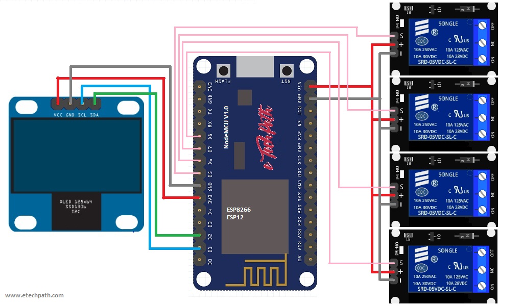
Circuit Diagram :
Source Code:
#include <ESP8266WiFi.h>
#include <WiFiClient.h>
#include <ESP8266WebServer.h>
#include <ESP8266mDNS.h>
#include <Adafruit_GFX.h>
#include <ESP_Adafruit_SSD1306.h>

#define OLED_RESET 4
Adafruit_SSD1306 display(OLED_RESET);


#if (SSD1306_LCDHEIGHT != 64)
#error("Height incorrect, please fix Adafruit_SSD1306.h!");
#endif

const char* ssid = "xxxxxxx"; //replace xxxxxxx with your wifi ssid
const char* password = "xxxxxxx"; //replace xxxxxxx with your wifi password

ESP8266WebServer server(80);

const int output1 = 14;
const int output2 = 12;
const int output3 = 13;
const int output4 = 15;

boolean device1 = false;
boolean device2 = false;
boolean device3 = false;
boolean device4 = false;

void handleRoot() {
//digitalWrite(led, 1);
//server.send(200, "text/plain", "hello from esp8266!");
//digitalWrite(led, 0);

String cmd;
cmd += "<!DOCTYPE HTML>\r\n";
cmd += "<html>\r\n";
//cmd += "<header><title>ESP8266 Webserver</title><h1>\"ESP8266 Web Server Control\"</h1></header>";
cmd += "<head>";
cmd += "<meta http-equiv='refresh' content='5'/>";
cmd += "</head>";

if(device1){
cmd +=("<br/>Device1 : ON");
}
else{
cmd +=("<br/>Device1 : OFF");
}

if(device2){
cmd +=("<br/>Device2 : ON");
}
else{
cmd +=("<br/>Device2 : OFF");
}

if(device3){
cmd +=("<br/>Device3 : ON");
}
else{
cmd +=("<br/>Device3 : OFF");
}

if(device4){
cmd +=("<br/>Device4 : ON");
}
else{
cmd +=("<br/>Device4 : OFF");
}

cmd += "<html>\r\n";
server.send(200, "text/html", cmd);
}

void handleNotFound(){

String message = "File Not Found\n\n";
message += "URI: ";
message += server.uri();
message += "\nMethod: ";
message += (server.method() == HTTP_GET)?"GET":"POST";
message += "\nArguments: ";
message += server.args();
message += "\n";
for (uint8_t i=0; i<server.args(); i++){
message += " " + server.argName(i) + ": " + server.arg(i) + "\n";
}
server.send(404, "text/plain", message);

}

void setup(void){
pinMode(output1, OUTPUT);
pinMode(output2, OUTPUT);
pinMode(output3, OUTPUT);
pinMode(output4, OUTPUT);

digitalWrite(output1, LOW);
digitalWrite(output2, LOW);
digitalWrite(output3, LOW);
digitalWrite(output4, LOW);

Serial.begin(115200);
WiFi.begin(ssid, password);
Serial.println("");


// by default, we'll generate the high voltage from the 3.3v line internally! (neat!)
//display.begin(SSD1306_SWITCHCAPVCC, 0x3D); // initialize with the I2C addr 0x3D (for the 128x64)
display.begin(SSD1306_SWITCHCAPVCC, 0x78>>1); // init done

display.clearDisplay(); // Clear the buffer.

display.setTextSize(2);
display.setTextColor(WHITE);
//display.setTextColor(BLACK, WHITE); // 'inverted' text
display.setCursor(0,0);
display.println(" ESP8266");

display.setTextSize(3); //Size4 = 5 digit , size3 = 7 digits
//display.setTextColor(BLACK, WHITE); // 'inverted' text
display.setTextColor(WHITE);
display.setCursor(0,18);
display.println("Control");

display.setTextSize(1);
display.setTextColor(WHITE);
//display.setTextColor(BLACK, WHITE); // 'inverted' text
display.setCursor(0,52);
display.println("Version 0.1");

display.display();
delay(2000);

display.clearDisplay();

display.setTextSize(2);
display.setTextColor(WHITE);
//display.setTextColor(BLACK, WHITE); // 'inverted' text
display.setCursor(0,0);
display.println("Connecting");

// Wait for connection
while (WiFi.status() != WL_CONNECTED) {
delay(500);
Serial.print(".");

display.print(".");
display.display();
}
Serial.println("");
Serial.print("Connected to ");
Serial.println(ssid);
Serial.print("IP address: ");
Serial.println(WiFi.localIP());

display.clearDisplay();
display.setTextSize(1); display.setTextColor(WHITE);
display.setCursor(0,0); display.println(ssid);
display.setTextSize(2); display.setTextColor(WHITE);
display.setCursor(0,18); display.println(WiFi.localIP());
//display.setCursor(0,36); display.println(WiFi.localIP());

display.display();

if (MDNS.begin("esp8266")) {
Serial.println("MDNS responder started");
}

server.on("/", handleRoot);

server.on("/status1=1", [](){
server.send(200, "text/plain", "device1 = ON");
digitalWrite(output1, HIGH);
device1 = true;
});

server.on("/status1=0", [](){
server.send(200, "text/plain", "device1 = OFF");
digitalWrite(output1, LOW);
device1 = false;
});

server.on("/status2=1", [](){
server.send(200, "text/plain", "device2 = ON");
digitalWrite(output2, HIGH);
device2 = true;
});

server.on("/status2=0", [](){
server.send(200, "text/plain", "device2 = OFF");
digitalWrite(output2, LOW);
device2 = false;
});

server.on("/status3=1", [](){
server.send(200, "text/plain", "device3 = ON");
digitalWrite(output3, HIGH);
device3 = true;
});

server.on("/status3=0", [](){
server.send(200, "text/plain", "device3 = OFF");
digitalWrite(output3, LOW);
device3 = false;
});

server.on("/status4=1", [](){
server.send(200, "text/plain", "device4 = ON");
digitalWrite(output4, HIGH);
device4 = true;
});

server.on("/status4=0", [](){
server.send(200, "text/plain", "device4 = OFF");
digitalWrite(output4, LOW);
device4 = false;
});

server.onNotFound(handleNotFound);
server.begin();
Serial.println("HTTP server started");
}

void loop(void){
server.handleClient();
}
Steps:
-
- Build up the circuit as shown in circuit diagram.
- Download source code from download section, edit downloaded code and input your home router’s SSID and Password in the code.
const char* ssid = "xxxxxxx"; //replace xxxxxxx with your wifi ssid
const char* password = "xxxxxxx"; //replace xxxxxxx with your wifi password
- Compile and upload the source code in NodeMCU or any ESP8266 you are using. You can use Arduino IDE to upload the code.
- Once your uploading process is completed, power up the circuit and reset the ESP once.
- Now ESP will connect to your router and it will show IP address of your ESP in OLED display.
- Install android application in your phone and open it, application link is given bellow in download section.
- Input IP address shown in OLED display and port i.e 80 in application page and hit connect button.
- Now you can operate relay from your phone and can connect any appliances to these relays. (consider relay amps rating )
Note: You can not use direct 5v relay in this project, because NodeMCU control output is only 3.3v which is not enough to trigger 5v relay. That is- why we are using relay module to work on this project.
Downloads: